When doing FE, you spend an awful lot of time assembling the model for the computer to analyse.
The main problem is that you can't accurately model the real world, you need to simplify, and deciding what you can simplify, and what's a reasonable simplification is a bit of an art. For example, in my wheel models described here, I have a perfectly rigid hub, with no deformation. I believe this to be reasonable, since the hub is a lot more solid and rigid than the spokes or the rim. I'm confident that distortion of the hub is insignificant compared to the deflection of the rim, so I don't need to model it.
A second problem is that you end up manipulating a lot of numbers, and controlling a lot of geometric entities trying to assemble your model. Some models have thousands, or tens of thousands of elements, and you need to make sure they all join up correctly, and that you haven't got some the wrong way round or upside down or whatever.
Number three - you decide you want to change the model. You think "I've done three cross spoking, how does two cross behave differently?" and you're back to your number two problem as you build your new model.
To address problem three (and therefor two), I didn't build these models directly. I wrote a program (in perl) that produced a command script (a series of instructions) that told my FE program how to build the model.
My script defaults to the arrangement on the main page - a 600mm diameter rim with the hub ends of the spokes on circles of 40mm diameter 50mm either side of the plane of the rim. The default pattern is 36 spokes in a 3cross pattern. My script is here and you're welcome to do what you like with it. Key parts are as follows (if you know perl this should be trivial to follow, the code even has comments!:
This sets up default options. It means you call the script as,
for example, build_wheel -c 2 if you want two cross.
A
little glitch (which I can't be bothered to fix) is that if you want
to specify a value of zero for anything you
need to use 00 not 0. For example, for radial spoking (zero cross) say
|
|
| 'Angle' is angle between each spoke position (in hub or rim) in radians. 'Degrees' is the same in degrees. | |
| This is the meat of it.
n is a count of spokes (counting from zero). rim_a is the count round the rim from top dead centre to the spoke we're considering. hub_a is the count from top dead centre at the hub, which depends on which spoke we're at and the number of crossings. The
|
|
The perl program produces a command file that looks like this for the default options.
(Note: if you're
reading this on a broken OS / browser combination that pays no
heed to security, it might
interpret 'open'ing that file as 'execute', because it has the
extension .cmd. It probably won't break anything if it
tries to run it, but you might like to copmlain to the manuufacturer
of your browser, since I could easily have embedded a format
c: in there.)
Once again, here's some commentary:
| Comments are good. | |
| Section properties and so on are elsewhere in a manually created command file. | |
| Defines a point at the rim end of the first and second spokes and a point half-way (around the arc) between them. | |
| Defines each spoke in turn. I've omitted the next 33 and trimmed some decimal places. | |
| The rim is made by defining the arc between the first and second spoke, then copying it round the circla as many times as needed. | |
| Selection sets let me easily select (for example) all the rim elements in one go, without having to click on each in turn. | |
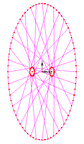
The geometry that produces looks something like this, where each point is shown as an enlarged red dot, and the lines a nice bright purple.
Note that these aren't the finite elements - the FE program I use
has an extra layer of abstraction on top of the elements. You
assemble the geometry, which is what is shown here, and it
then puts in the elements on the basis of this. For example, while
the geometry
has one line extending from one spoke to the next round the rim, the
program splits the one line into five elements joined end-to-end.
There are various reasons why this extra abstraction is considered a
good idea. Sometimes it is, sometimes it causes confusion and gets in
the way of what I want to do.
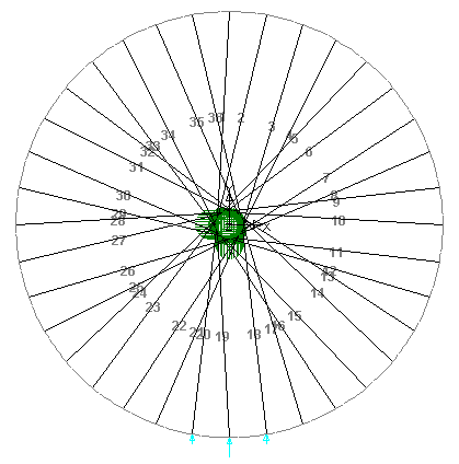
Spokes are numbered like this.
In use, this system lets me get a working model of almost any wheel very quickly:
build_wheel > foobar.cmd with whatever
parameters I want.
foobar.cmd.
back to the main wheel analysis page
back to www.astounding.org.uk top contents
page
To comment on anything (please do) email ian@astounding.org.uk